Cable Tester

Company: NCR Canada Ltd.


Parts
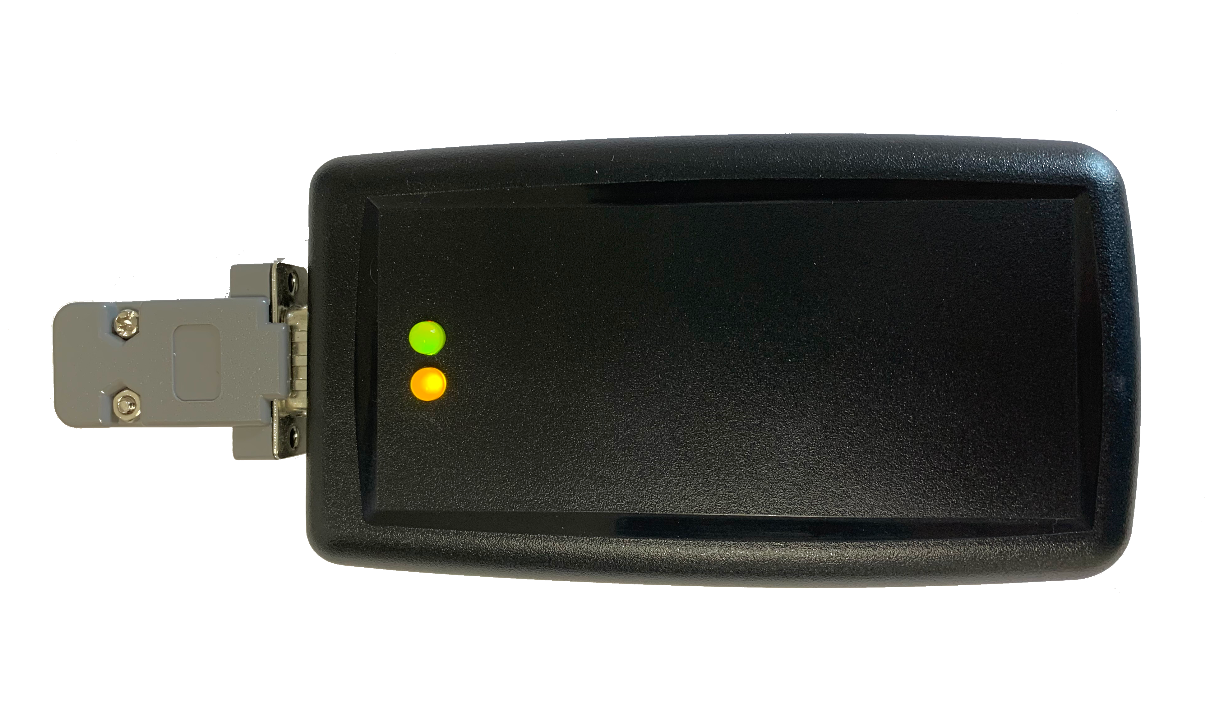
- During an upgrade project for the Lottery contract, several problems were encountered. After site conversions for the Keno Displays (LED message boards), Lottery Ticket terminals had some issues with their peripherals. These issues were due to serial communication problems via RS232 specifications. There was a need to address these mistakes promptly since possibly thousands of remote sites needed corrections.
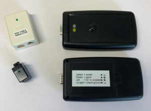
- This build was entirely designed and manufactured in-house, with components sourced locally and circuit boards commercially printed. Multiple units were handcrafted and then tested. It's worth mentioning that I had constructed three prototypes before finalizing the design.
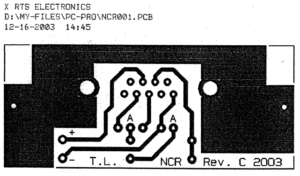
- To ensure user-friendly operation, a simple cat and mouse design was employed. The creation of the circuit board involved the use of a cost-free PCB design software. To indicate the testing results, a multi-color LED was utilized, displaying green for a positive outcome and red for a negative one. Considering the lack of technical expertise among the field representatives, cabling pin out diagrams were not anticipated to be that difficult a task, and a substantial number of sites required conversion. Despite extensive documentation, communication issues persisted for RS232 devices post-site conversion.
- The cat and mouse design was selected because the LED Message display could be placed up to 100 feet away from the terminal and ran along the existing building infrastructure. This eliminated the need to install new cables when only the ends were changed.
- Due to the tight deadline, the original project was briefly put on hold to accommodate the development of a custom tool for this specific task. Within a two-week timeframe, the team(me) focused their efforts on testing and constructing this new tool to meet the project's demands.
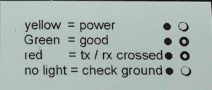
- The non-standard cable end used in the cabling posed several challenges. Firstly, it hindered the use of readily available cable testing devices. These devices were not only expensive at the time, but also required a common understanding of their operation. The interpretation of the output from these devices was not straightforward, unlike a simple "Green = Good" or "Red = Bad" indication, making it difficult to ensure consistent and accurate testing results.
- Additionally, the lack of standardization in the cable end meant that it was not compatible with the standard testing equipment and procedures used in the industry. This resulted in the need for specialized tools and techniques, further increasing the complexity and cost of testing. The absence of a common understanding of the operation of these devices also contributed to potential misinterpretations and errors, leading to unreliable test results.
- Moreover, the non-standard cable end limited the ability to easily troubleshoot and diagnose cable-related issues. Without compatible testing equipment, it became more challenging to identify and resolve problems with the cabling, potentially leading to longer downtime and reduced operational efficiency.
- To address these challenges effectively, customized testing solutions were necessary, involving the development of specialized testing equipment and the establishment of clear and standardized procedures for operating these devices. This would have required collaboration among stakeholders, including manufacturers, service providers, and end-users, to ensure a common understanding and consistent approach to cable testing.
- In this innovative design, a crucial test was conducted to ensure the proper connection of the ground. The device was engineered in such a way that it would neither power up nor display any lights if the ground connection was incorrect. This rigorous testing process aimed to prevent any potential issues or malfunctions that could arise from an improper ground connection.
- Furthermore, the design meticulously verified the correct orientation of the Transmit and Receive lines, ensuring optimal signal transmission and reception. Additionally, it thoroughly checked the grounding of the cable to minimize interference and maximize the reliability of the connection. These comprehensive tests ensured the device's functionality and integrity, providing a robust and reliable system for various applications.
- By incorporating these rigorous testing procedures, the designers aimed to deliver a product that not only met the required specifications but also exceeded expectations in terms of performance and durability. The emphasis on proper grounding and correct orientation of signal lines demonstrated a commitment to quality and attention to detail, ensuring a seamless user experience and minimizing the risk of unexpected issues.


Parts
- 1 x 100 ohm resistor
- 1 x 1 K ohm resistor
- 1 x 2.2 K ohm resistor
- 1 x Dual color LED
- 1 x Yellow LED
- 1 x Green LED
- 1 x Circuit board
- 1 x RJ11 female adapter
- 1 x 9 pin male adapter board mount
- 1 x Hobby Case
- 1 x 9 volt battery